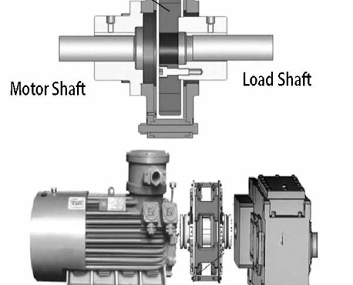
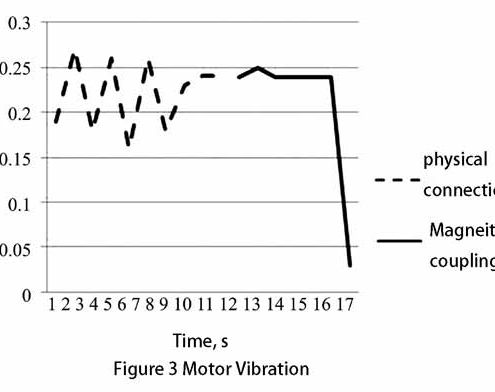
The magnetic motor coupling we are talking in the page is disc magnetic coupling. Unlike traditional couplings, magnetic motor couplings rely on magnetic fields to transmit torque rather than physical machinery. Based on this principle, the magnetic motor coupling has an excellent performance: it can withstand large deviations and will not conduct vibration and heat, less noise.
Magnetic motor coupling Technology in Soda Plant
Magnetic motor coupling solves the problem of frequent oil leakage, fusible plug melting and bearing failure of the hydraulic coupling, which leads to the emergency shutdown of the calciner and seriously affects the soda production.
A soda plant has an annual production capacity of 300,000 tons of soda ash and 300,000 tons of ammonium chloride. Three self-returning steam rotary calciners are used in the production, including 2 light ash furnaces, 1 heavy ash furnace, and 2 light ash furnaces. The ash furnace can work at full capacity at the same time. The connection equipment between the main motor of the calciner and the reducer is a hydraulic coupler, but in actual operation, due to frequent equipment accidents of the hydraulic coupler, the production load cannot go up, and the half-load operation is repeated many times, which seriously affects the connection. The long-term and optimal operation of the alkali plant.
1 The working principle and use status of the hydraulic coupler
1.1 Working principle of hydraulic coupling
Hydraulic coupling is a kind of non-rigid coupling with liquid as working medium, also known as hydraulic coupling. The pump wheel and the turbine of the hydraulic coupler form a closed working chamber that can circulate the liquid, the pump wheel is mounted on the input shaft, and the turbine is mounted on the output shaft. When the power machine (internal combustion engine, electric motor, etc.) drives the input shaft to rotate, the liquid is thrown out by the centrifugal pump wheel. After this high-speed liquid enters the turbine, it drives the turbine to rotate, and transfers the energy obtained from the pump wheel to the output shaft. Finally, the liquid returns to the pump wheel, forming a cycle of flow. The hydraulic coupling relies on the interaction of the liquid with the blades of the pump impeller and the turbine to generate the change of the momentum moment to transmit the torque. Its output torque is equal to the input torque minus the friction torque, so its output torque is always less than the input torque. The input shaft and the output shaft of the hydraulic coupler are connected by liquid, and there is no rigid connection between the working components.
1.2 Current situation of hydraulic coupling
During the 5-year operation, the hydraulic coupler frequently experienced oil leakage, fusible plug fusion, bearing failure, and high oil temperature failures, resulting in system load-shedding production. Fees have risen sharply.
2 Composition, working principle and advantages of magnetic motor coupling
The alkali plant tried to replace the current hydraulic coupler with a new magnetic motor coupling technology, and applied the magnetic motor coupling technology to the calciner of a large-scale device for the first time. They conducted research on coal mining enterprises that have adopted magnetic motor coupling technology. The hydraulic coupling originally used in the alkali plant was opened for inspection or maintenance every week on average due to vibration and oil leakage. So far, no maintenance has been carried out, and the stability is extremely high. As a magnetic motor coupling manufacturer, we have inspected the three calciners in the alkali plant on-site and indicated that the transformation conditions are available.
2.1 Composition and working principle of magnetic motor coupling
Conductor disk (copper disk or aluminum disk) (connected with motor shaft), permanent disk (connected with load shaft), only rely on magnetic motor coupling to transmit torque, without any mechanical connection between motor and load, see Figure 1. At rest, the conductor disc is in the magnetic field generated by the permanent magnet. When the conductor disk rotates with the motor shaft, the conductor disk will cut the magnetic field lines, thereby generating eddy current on the conductor disk, which in turn will generate an induced magnetic field, and a magnetic field will be generated between the induced magnetic field and the magnetic disk of the magnet disk. The force of the movement, thereby realizing the torque transmission between the motor and the load.
2.2 Advantages of magnetic motor couplings
2.2.1 Speed regulation (speed regulation type)
According to the requirements of the process, the air gap of the magnetic coupler can be adjusted to realize speed regulation and achieve the purpose of energy saving and environmental protection. During adjustment, the speed of the motor remains unchanged, and it still runs under the sine wave of 50 Hz, so it will not produce a series of problems caused by higher harmonics.
2.2.2 Soft start of magnetic motor coupling
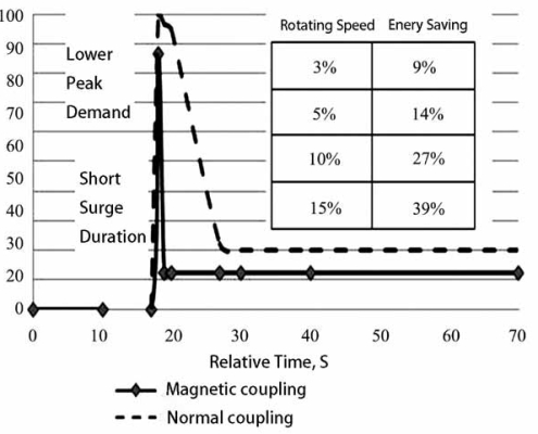
After using the magnetic motor coupling, the startup is smooth, which reduces the impact of the impact load during startup and operation, and prolongs the service life of the equipment. When the motor directly drives the load, the whole process from the motor startup to the load startup is completed at one time. After installing the magnetic coupler drive, the whole starting process becomes two stages: the first stage of the motor firstly rotates the conductor rotor with the magnetic coupler, and the second stage the conductor rotor of the magnetic coupler drives the permanent magnet rotor to start at a constant speed. Therefore, the whole starting process is stable, the impact is small, and it has the characteristics of soft start/soft stop, which can effectively reduce the starting current of the motor.
2.2.3 Magnetic motor coupling save energy
The motor can always work in the maximum efficiency area, and it will not fluctuate greatly due to changes in the load. The speed of the load can be adjusted according to the system operating conditions, which can save a lot of electric energy. According to the analysis of working conditions on site, the average annual power saving rate will be above 15%.
2.2.4 Magnetic motor coupling reduce vibration
1) The vibration amplification transmission of rigid couplings is greatly reduced. The magnetic motor coupling replaces the original rigid coupling, so that there is no mechanical connection between the motor and the load, so that the vibration of the load side will not be transmitted to the motor side, and the vibration of the motor side will not be transmitted to the load side. At the same time, the amplification effect of vibration in the transmission process is cut off, so the vibration amplification effect of the rigid coupling can be eliminated and the vibration of the system can be reduced.
2) System vibration caused by shaft bending and thermal expansion can be greatly reduced.
2.2.5 Significantly extend the time between failures and reduce the rate of failures.
The magnetic motor coupling basically does not fail. Because the torque is transmitted by the air gap, there are no wearing parts, which greatly reduces the vibration in the system, so that the bearings and shaft seals can be used in more Good operating point operation prolongs the service life of the motor and load, thereby reducing downtime and improving the utilization rate of dynamic equipment.
2.2.6 With overload protection
During the operation of the equipment, system overload or locked rotor often occurs, which causes the motor to be burned. After the magnetic motor coupling is installed, it has buffering and protection functions for the equipment with impact load and may be locked, reducing the damage of the motor due to overcurrent. Damage occurred.
2.2.7 Simple installation, less maintenance work, basically maintenance-free
2.2.8 Strong ability to adapt to the environment
It is suitable for various environments, and can be used in harsh environments such as high temperature, low temperature, high dust, high altitude, high humidity, flammable and explosive. 26 Soda Ash Industry
3 Magnetic motor coupling transformation situation
| Table 1 Main equipment parameters of the original drive unit | ||
| Motor | Reducer (SEW) | Hydraulic coupling (Dalian Longyuanda) |
| Model: YKK450-4 | Model: M3PSF70+FAN (double input and single output) | Model: YOX650 (with coupling total length 556 mm,Maximum outer diameter 760 mm) |
| Power: 220 kW | Rated power: 454 kW | Oil charge: 21~48 L |
| Speed: 1 482 r/min | Rated speed ratio: 31.5 (actual speed ratio 30.889) | Efficiency: 96% |
| Output shaft diameter: φ120m6×210 | Service factor: 2.55 (shaft power 178 kW) | Input shaft diameter d1: φ120×210 Output shaft diameter d2: φ65×125 |
| Voltage class: 10 kV | High-speed shaft diameter: φ65m6×125 | Weight: 230 kg |
| Table 2 The main parameters of the magnetic coupling | |||||||
| Model | Transmission Power | Weight | Efficiency | Overall Length | Max Outer Diameter | Medium: | Operating Temperature |
| Original hydraulic coupler YOX650 | 260~480 kW | 230 kg | 86% | 556 mm | 760 mm | Oil 24~48 L | -15~50 ℃ |
| Permanent magnet coupler DYT-X220 | 2836 Nm | 190 kg | ≥97% | 420 mm | 565 mm | Air | -40~+100 ℃ |
According to the original equipment parameters, it was transformed and replaced with a torque-limiting magnetic motor coupling.
1) The distance between the original motor shaft and the shaft end of the reducer is 221mm (556-210-125 mm). After the permanent magnet is transformed, the distance between the motor shaft and the shaft end of the reducer is about 187mm, that is, the motor can move forward about 36mm in the direction of the reducer.
2) Keep the center height of the original drive part (including motor and reducer) unchanged.
3) After the transformation, the motor and reducer can tolerate a larger installation alignment error, which makes the installation work easier and the workload of debugging during transformation is smaller.
| Table 3 Comparison of effects before and after transformation | ||
| Comparison Term | Permanent Magnet Coupler | Hydraulic Coupler |
| Gross weight | DYT-X220 gross weight 190 kg | YOX650 gross weight 230 kg |
| Maintainability | ① The permanent magnet coupler has no bearings and seals, and does not need to be lubricated; | ① There are bearings and seals inside the hydraulic coupling, which are prone to oil leakage and other faults, and require regular maintenance; |
| ②The alignment is simple; | ②The hydraulic coupling needs to be replaced/supplemented with hydraulic oil regularly; | |
| ③The overload capacity is strong, and once overloaded, the permanent magnet coupler has better recovery; | ③ The requirements for centering are very high; | |
| ④It has better torque limit protection function. | ④Once the hydraulic coupling is overloaded, a large amount of hydraulic oil will be leaked when the fusible plug bursts, causing ground pollution, and it will form sludge after mixing with dust, which is not easy to clean, and there is a danger of explosion if the temperature and pressure rise sharply. | |
| Maintenance cost | Relying on the space magnetic field to transmit torque, there is no direct physical contact, and it is basically maintenance-free. Only regular inspection of bolt tightening is required, which will not affect production. | ①The maintenance cost is about 6 times a year due to oil leakage bearing failure, and the cost of each maintenance and replacement of lubricating oil is about 20,000 yuan. ②Half-load production is about 24 hours each time, and the production of soda ash and 500t of ammonium chloride will be reduced by 500t. Calculated by more than 2,500 yuan per double ton, the annual sales income will be reduced by 7.5 million yuan. |
4 After switching to magnetic motor coupling
No matter in normal operation or in the process of starting and stopping the calciner after the transformation, the magnetic motor coupling shows absolute advantages, there is no abnormal phenomenon, the starting current drops by about 20%, the running sound is reduced, the motor and deceleration Machine vibration is reduced. The most important thing is that there is no oil leakage and zero failure phenomenon, basically maintenance-free, and the transformation achieves the expected goal.
Before the transformation, the calciner was shut down for maintenance on average every 2 months due to oil leakage of the hydraulic coupler, bearing failure, and the coupler’s temperature was too high and the fusible plug melted. During the half-load production period, it was about 24 hours. The annual maintenance cost of the motor and reducer due to the failure of the coupler is about 150,000 yuan. After the renovation, there was no system reduction phenomenon due to the failure of the coupler, and the calciner ran smoothly.


