Coupling is a typical representative of mechanical protection and is often used in the coal preparation process. At present, the torque limited hydraulic coupling is the most widely used. However, in practice, the protection is delayed or not protected, the fusible plug does not inject oil, the fusible plug pollutes the environment after oil injection, the oil pollution is difficult to deal with, and the displacement is damaged. It often troubles users and needs to be solved urgently. In recent years, a new type of torque limited magnetic coupling has appeared, with good user feedback, but less application. According to the principle of Lenz’s law, the mining torque limited magnet coupling transfers energy through the interaction between the rotating permanent magnet magnetic field and the induced magnetic field, and realizes the transmission from the motor to the reducer through the air gap between the conductor and the permanent magnet. The torque transmission device realizes the contactless transmission mode between the motor and the reducer. This unique advantage completely isolates the motor and the reducer, and will not cause vibration and damage due to the misalignment of the axes. The equipment damage accident caused by the reduction of strength; at the same time, when the load has an impact, it can reduce the load speed and increase the load torque to buffer the impact force and protect the equipment. It has been found in practice that the most necessary situation for mechanical protection is when the crusher is blocked, the torque limited magnet coupling can instantly cut off the torque transmission between the motor and the reducer to ensure that the motor and the reducer are not damaged. In this paper, the performance of the magnetic coupling is verified through experiments and application analysis.
1 Basic structure and principle analysis of moment-limited magnet coupling
1.1 Basic structure
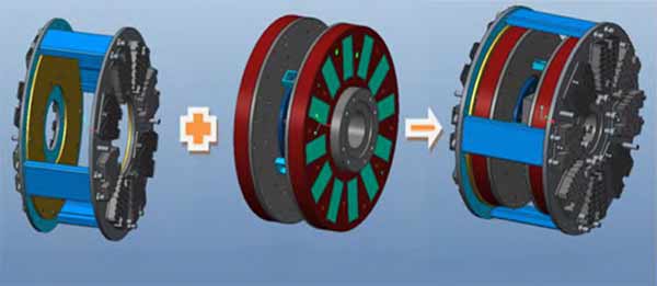
The torque limited magnet coupling is composed of multi-stage permanent magnet rotor, induction rotor, permanent magnet rotor inner sleeve and induction rotor conductor, etc. See Figure 1 for details.

Fig.1 Basic structure of torque limited magnet coupling
- 2 Installation method
The flange of the induction rotor is connected with the drive motor, and the inner flange of the permanent magnet rotor is connected with the load.
1.3 Operating principle
When the multi-pole permanent magnet rotor and the induction rotor move relative to each other, eddy currents are generated on the conductors of the induction rotor to generate a magnetic field, and the two magnetic fields interact to drive the load to rotate; when the set locking torque is reached, the two multi-pole permanent magnetic The magnetic rotor and the induction rotor repel each other, and the two multi-pole permanent magnet rotors slide inward on the inner sleeve of the permanent magnet rotor, away from the induction rotor, thereby disconnecting the connection and the load losing power.
2 Experimental studies
The test uses a double-toothed roller crusher. The test method is a loading test. It is equipped with a 160kW torque limited magnet coupling, and the rated output torque of the 160 kW 4-pole motor is 1024 N m. The torque limited magnet coupling is adjusted to The induction rotor and the permanent magnet rotor are in the state of 3% slip, and the output torque is 1024 N·m, which is designated as the rated state.
2.1 Test conditions The specific test conditions are shown in Table 1.
| Table 1 Test conditions | |||||
| Working Temperature/℃ | Drive motor/kW | Motor rated speed /( r·min-1 ) | Maximum load /( N·m) | Motor rated torque /( N·m) | Loader maximum torque/( N·m) |
| 16 | 160 | 1488 | 2500 | 1024 | 2000 |
2.2 Loading test
During the test, the induction rotor of the torque limited magnet coupling is installed at the end of the drive motor, and the permanent magnet rotor is installed at the load end.
| Table 2 Corresponding relationship between loading test torque data | |||||||||||||
| Slip/r | 15 | 30 | 45 | 60 | 75 | 90 | 105 | 120 | 135 | 150 | 160 | 165 | 180 |
| Motor Torque/( N·m) | 367 | 795 | 1028 | 1235 | 1346 | 1443 | 1502 | 1560 | 1613 | 1662 | 32 | 28 | 26 |
| Load Torque/( N·m) | 346 | 762 | 1043 | 1246 | 1403 | 1486 | 1547 | 1625 | 1677 | 1746 | 12 | 12 | 11 |

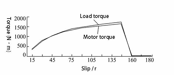
The torque change curve is shown in Figure 2.
According to Table 2, when the slip is 45 r, the output torque of the motor is 1028 N m, which is set as the rated power of the coupling; it can be seen from the graph: when the load is continued to the slip 150 r , the torque limited magnet coupling is disengaged instantly, the transmission power basically tends to zero, and the motor power is also reduced to a minimum at this time. In the actual use process, the crusher stall occurs basically in an instant, so at the moment of disconnection, the input torque of the motor is 1662 N m, which is 1.62 times the rated torque of the motor, and the load torque is 1 746 N·m, which is 1.7 times the rated torque of the motor; lower than the design stall torque of the motor, which can protect the motor and reducer well.
| Table 2 Corresponding relationship between loading test torque data | |||||||||||||
| Slip/r | 15 | 30 | 45 | 60 | 75 | 90 | 105 | 120 | 135 | 150 | 160 | 165 | 180 |
| Motor Torque/( N·m) | 367 | 795 | 1028 | 1235 | 1346 | 1443 | 1502 | 1560 | 1613 | 1662 | 32 | 28 | 26 |
| Load Torque/( N·m) | 346 | 762 | 1043 | 1246 | 1403 | 1486 | 1547 | 1625 | 1677 | 1746 | 12 | 12 | 11 |
2.3 Feasibility of determining power parameters under different slip
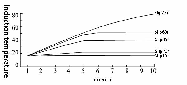
In order to ensure the reliability of the product, the temperature conditions of the product in various states are tested to verify the feasibility of determining the power parameters. Therefore, under different slips, the corresponding temperature of the induction plate is tested at different times. The test data is shown in the table. 3. According to Table 3, the relationship between the temperature and time of the induction plate under different slips is shown in Figure 3.
Table 3 Corresponding temperature of time-sensitive disc/℃ under different slip
| Time/min | |||||||||||
| Slip/ r | 0 | 1 | 2 | 3 | 4 | 5 | 6 | 7 | 8 | 9 | 10 |
| 15 | 16 | 16.6 | 16.8 | 17 | 17 | 17 | 17 | 17 | 17 | 17 | 17 |
| 30 | 16 | 17.2 | 18.4 | 20.4 | 22.3 | 22.4 | 22.3 | 22.4 | 22.3 | 22.4 | 22.2 |
| 45 | 16 | 22.1 | 28.2 | 34.4 | 39.2 | 40.2 | 40.4 | 40.3 | 40.3 | 40.2 | 40.3 |
| 60 | 16 | 24.5 | 32.1 | 40.3 | 48.2 | 51.2 | 51.2 | 51 | 51.2 | 51.1 | 51.2 |
| 75 | 16 | 26.2 | 35.4 | 43.1 | 51.3 | 58.6 | 65.2 | 70.8 | 75.1 | 79.6 | 83.1 |
Fig.3 The relationship between the temperature and time of the induction plate under different slips

It can be seen from Figure 3 that when the slip is within 60 r, the temperature of the induction disc can self-balance after a certain period; when the slip is higher than 75 r, the temperature keeps rising. To be considered, because the temperature of the product should be controlled not to be higher than 80 ℃; it is reasonable to choose the slip of 45 r as the benchmark for determining the power of the torque-limited magnet coupling.
3 Experimental verifications of the torque limited magnet coupling and the hydraulic
Differences and Advantages
The test equipment is a double-drive roller crusher, equipped with 2 motors (drive power 660 V, motor power 160 kW) and 2 SEW reducers; the hydraulic coupling used in the original installation of the equipment is now 2 torque limiting The magnet coupling is installed between 2 motors and 2 reducers respectively, to ensure the reliable positioning of the reducer and the motor, and make the magnetic field air gap of the torque limiting magnet coupling uniform. During the operation of the crusher, the load is uneven, so it is necessary to observe and record the data for a long time.
- 1 2 kinds of transmission matching input and output vibration changes
After the torque limited magnet coupling is installed and used, the vibration situation of the actual monitoring equipment under heavy load is compared with the situation of the original hydraulic coupling. It can be seen from Table 4 that after replacing the magnetic coupling, the same Compared with the coupling, the vibration values (vibration intensity and vibration displacement) of the motor and reducer are greatly reduced.
Table 4 Vibration values of motor and reducer before and after use
Motor vibration value
| Table 4 Vibration values of motor and reducer before and after use | |||||
| Motor vibration value | Reducer vibration value | ||||
| Vibration Intensity /( mm·s-1 ) |
Vibration Displacement/μm | Vibration Intensity /( mm·s-1 ) |
Vibration Displacement/μm | ||
| Before | 4.6 | 95 | 6.5 | 105 | |
| After | 2.6 | 57 | 4.2 | 66 | |
By monitoring the vibration data of the equipment for a long time, the vibration value of the motor and the reducer fluctuates less, and the stability of the equipment is further improved.
- 2 2 Variations of Transfer Stall Current
Through loading, when the load is locked, the motor locked-rotor power is collected.
Flow data, see Table 5 for data comparison.
| Table 5 Motor current data when the motor is locked | ||||
| Times | 1 | 2 | 3 | 4 |
| Hydraulic Coupling/A | 670 | 684 | 664 | 687 |
| Magnetic Coupling/A | 331 | 322 | 341 | 326 |
The rated voltage of the motor configured in the test is 660 V and the rated current is 178 A. It can be found from Table 5 that the instantaneous locked-rotor current using the torque limited magnet coupling is 1.85 times the rated current, which is higher than that of the original hydraulic coupling. The locked rotor current is reduced by about 50%, which greatly reduces the input current of the motor when the crusher is locked; it also greatly reduces the damage to the motor and the reducer by the impact force, which can greatly extend the service life of the motor and the reducer. ; This is not possible with the hydraulic coupling. The data is also basically consistent with the test data when the locked-rotor torque reaches 1.7 times the protection. At the same time, it can be seen from Table 5 that when the equipment is locked, the input current transmitted by the hydraulic coupling is much larger than that transmitted by the magnet coupling. The reason is not difficult to find: the protection of the hydraulic coupling is that in the case of large slip, the liquid in the hydraulic coupling consumes power and generates heat. It takes a certain amount of time to start the power transmission, and it cannot be disconnected instantly, so it requires a large amount of power input from the motor to complete it, which may cause damage to the equipment and stop production in the process.
- 3 2 Variations of the rotational speed of the transmitted load
In daily observations, when the crusher has an impact load that does not exceed the protection torque of the magnet coupling, the load speed decreases rapidly (from the test data in Table 2, it is shown that the load torque increases greatly, which is higher than the actual motor output. Large torque), effectively reducing the impact of the load, this flexible connection is very suitable for the operation of the crusher, this function is equivalent to the hydraulic coupling.
3.4 2 Variations of the transmitted load torque
According to the data analysis of the test in Table 2, the magnet coupling gradually increases the load torque when the slip gradually increases, which is conducive to improving the effect of the crusher on impacting materials that are not easily broken, while the hydraulic coupling There is no instantaneous variability.
3.5 Differences after replacing the two transfer protections
The coupling medium used by the hydraulic coupling is polluted by the environment, and at the same time, the high-temperature liquid is ejected, and there are also potential safety hazards; after the hydraulic coupling is protected, it needs to manually add liquid and replace the fusible plug. The device does not have these problems, and the protection will automatically return to the original state after the shutdown, which is simple and safe to use.
3.6 Test conclusion
Through experimental research and application analysis, it is not difficult to see that the torque limited magnet coupling has outstanding advantages over the torque limited hydraulic coupling due to its special principle. It not only solves the problem of untimely or even unprotected hydraulic protection but also prevents hydraulic The problem that the force coupling injects fuel to pollute the environment and the subsequent disposal is difficult; at the same time, the torque-limited magnetic coupling can well avoid displacement damage and rupture; it solves many problems that cannot be solved by the hydraulic coupling, regardless of safety protection. In terms of environmental protection, it is far superior to hydraulic coupling, and it is a good replacement and upgrade product for hydraulic coupling.
4 Conclusion
The torque limited permanent magnet coupling technology has been well used in coal preparation equipment, especially in the transmission system of crushers and large belt conveyors, which are the key equipment for raw coal preparation. The embarrassment greatly reduces the labor intensity of worker replacement, escorts the subsequent coal preparation process, and provides a strong guarantee for the continuity of coal preparation production.
[/av_textblock]
